MusicBox Project Introduction
July 2024
Welcome, I am David! I am a husband, Dad, and engineer. I think that computer programming is fun, especially when I get to write code "close to the metal" (directly interacting with electronics).
My MusicBox project is about using the electronics parts I had laying around in my office to build a small device that would play music and sound effects on small speakers. I'm doing this for fun and learning, and also to share my experiences with other people who might be interested.
These are the main parts of the website:
- Construction - instructions for how to build my MusicBox device. Mostly for future me, but hopefully helpful to others as well.
- Programming - the software I wrote to power the MusicBox
- Design - explanation of how it works and why I made some of the design choices. This is intended to be somewhat educational for those interested.
Enjoy!
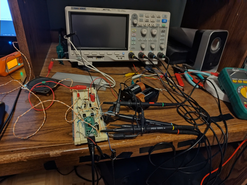
This is my little workshop when I was developing the Music Box device:
QR code for sharing this website:
Construction
Parts List
- Raspberry Pi Pico microcontroller board
- A 3.3V-compatible USB-to-serial adapter. I recommend USB to TTL Serial Cable Debug / Console Cable for Raspberry Pi from Adafruit.
- A breadboard for plugging parts into and wiring them up. Something like this breadoard from Micro Center would work just fine.
- Wires for connecting pins on a breadboard. Being frugal, I use random small guage wire that I scavenge from various sources. They need to be the right thickness to plug into the breadboard holes. You can buy breadboard jumper wires made for the purpose. You'll need about 30 wires of various lengths.
- 2 2N4403 transistors
- 2 2N4401 transistors
- 4 general-purpose silicon diodes, like 1N4001
- 4 1K-ohm resistors
- 2 breadboard-friendly bushbutton switches, like these switches from Sparkfun
- 1 breadboard-friendly single-pole double-throw switch able to handle 200mA, like Mini Power Switch from Sparkfun
- 1 small 8-ohm speaker rated between 250mW and 1W, like this speaker from Mouser
- Battery holder for 2 D-sized batteries
- 2 D-sized batteries
- Solder for a couple of small soldering jobs
The amount of soldering I did on this project is extremely minimal. Mainly I just soldered two wires onto the speaker so I had some way to connect it to the breadboard. Your battery holder will need wires soldered to it if it doesn't already have them.
Part substitutions:
Batteries
I don't think I needed D-sized batteries. AA batteries might work. They have to supply about 200mA current at 3V. The batteries just supply the current through the speaker. The microncontroller is powered via a USB connector.
Transistors
The 2N4403 and 2N4401 BJT transistors are listed as "obsolete" on some websites. I'm using some left over from my Electrical Engineering student days from the 1990s. The main thing is to use complementary PNP / NPN BJT transistors that can are rated at 600mA and don't have a turnoff time much higher than 225 ns. I use the BJTs in full-saturation switching mode in an H-bridge configuration. The software I wrote assumes a 225 ns turn-off time to avoid shoot-through on the H-bridge. If you substitute transistors that turn off much more slowly than that, then you will need to tweak my software to have a longer dead time when switching, or your circuit will burn up.
I am using BJTs instead of MOSFETs because I could not find MOSFETs that met my requirements:
- Must be breadboard-friendly with pins at 0.1" / 2.54mm pitch
- Must quickly switch on and off up to 200mA current
- Must turn fully on with only 3.3V Vgs
Everything I found when searching for MOSFETs either needed 5V Vgs or higher to turn fully on, had a large gate capacitance such that the microcontroller couldn't switch them quickly, or were surface-mounted parts unusable on a breadboard. You can buy MOSFET drivers to handle the high gate capacitance and level shift from 3.3v to the required gate voltage. But with that additional cost and space and complexity, I might as well just buy an audio amplifier - defeating the whole purpose of this project, which is to build my own!
So I'm using my old BJTs as switches and they work just fine.
Wire Connections
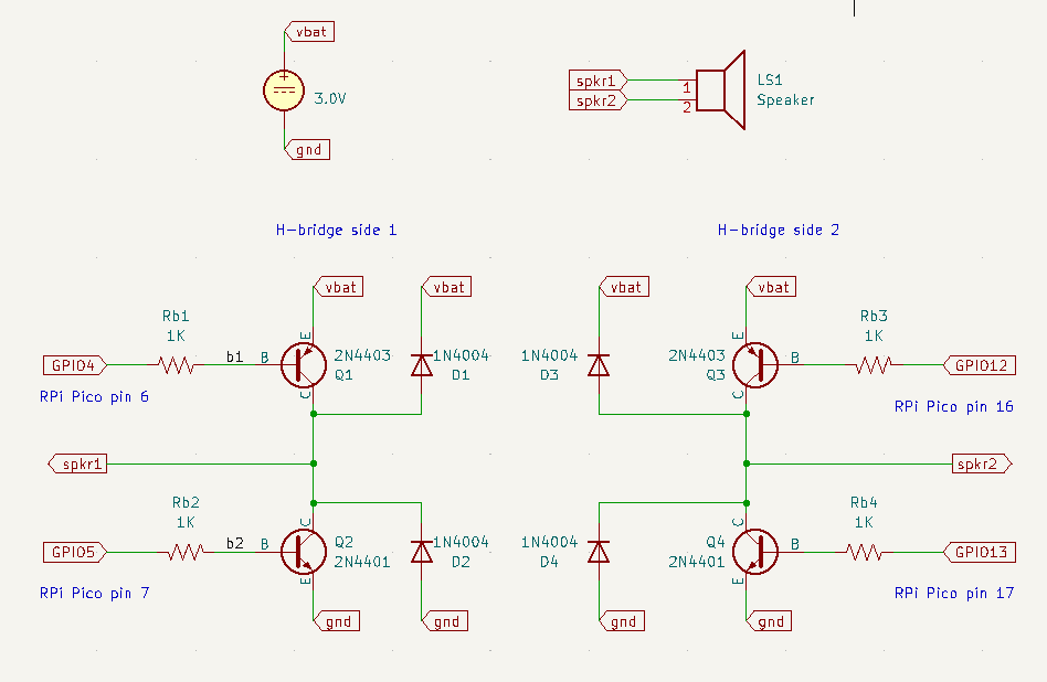
Speaker Driver Schematics
Raspberry Pi Pico pin diagram

Connections to make on Raspberry Pi Pico
Pin 1 (UART0 TX): white wire on USB-to-serial adapter (host RX)
Pin 2 (UART0 RX): green wire on USB-to-serial adapter (host TX)
Pin 3 (GND): black wire on USB-to-serial adapter (host ground)
Pin 6 (GPIO4): to resistor driving Q1 (see schematic)
Pin 7 (GPIO5): to resistor driving Q2 (see schematic)
Pin 8 (GND): battery ground
Pin 16 (GPIO12): to resistor driving Q3 (see schematic)
Pin 17 (GPIO13): to resistor driving Q4 (see schematic)
Pin 18 (GND): battery ground
Pin 28 (GND): battery ground
Pin 29 (GPIO22): app pushbutton. Connect other side of pushbutton to ground.
Pin 30 (RUN): reset pushbutton. Connect other side pushbutton to ground.
If you are going to program the Pico, connect it to a host PC via USB cable.
If the Pico is already programmed, then you can connect it to either a PC or to a power adapter. Either way, the Pico gets its power via its USB connection.
Other connections
The battery holder holds 2 D batteries in series. The black wire is ground, the red wire is +3 volts. (assuming your battery holder uses standard wire colors.)
The single-pole double-throw (SPDT) switch is used as a on-off switch for the battery. It has 3 pins that I'll call top, middle, and bottom. Connect top to battery red, middle to the red power row the breadboard, and bottom to nothing.
Connect the battery black wire to the ground row on both sides of the breadboard.
Connect one of the speaker wires to the H-bridge side 1 spkr1 output (see schematic) and the other speaker wire to the H-bridge side 2 spkr2 output (see schematic).
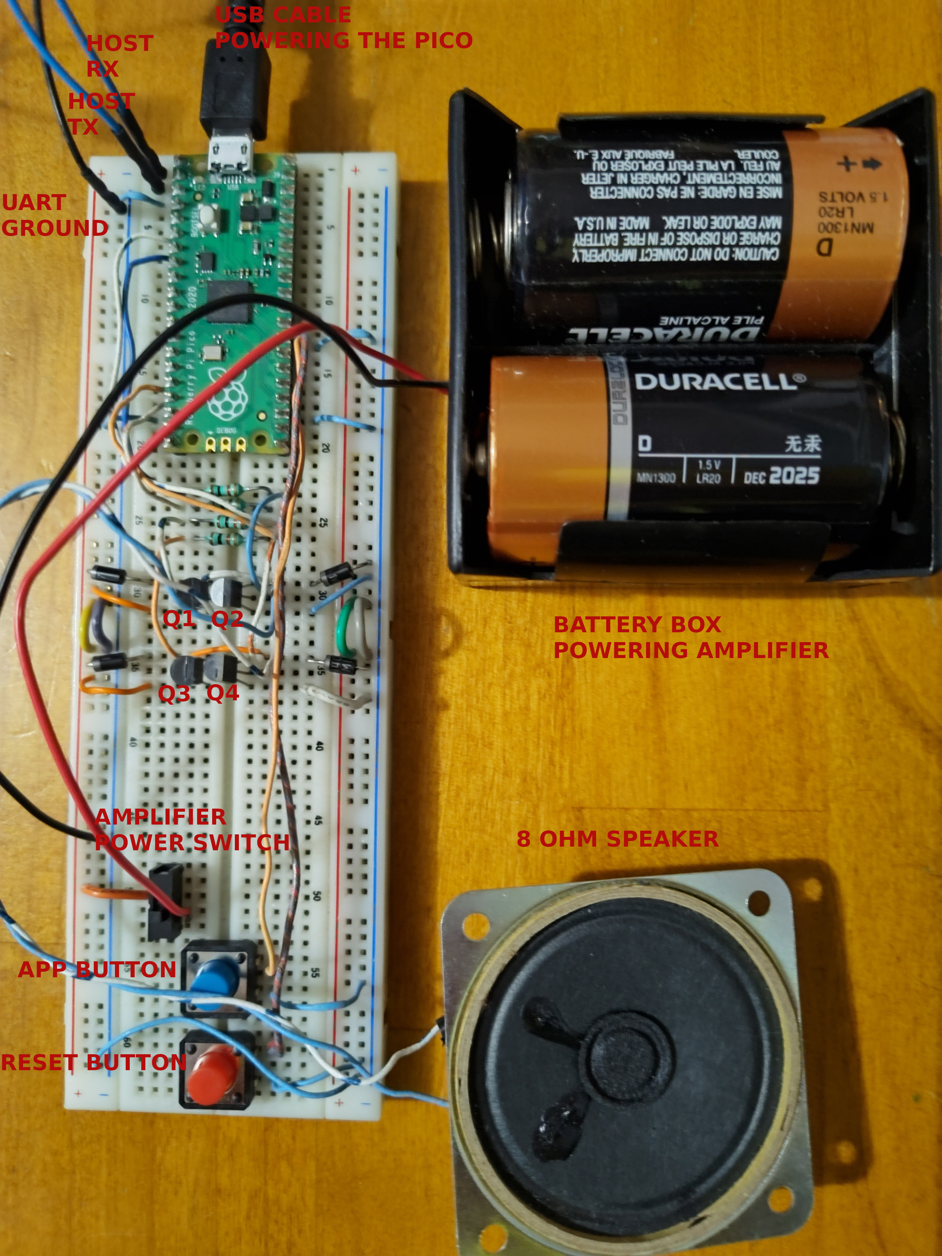
Final Assembly
Don't worry that the "host RX" and "host TX" wires shown in the picture below are both blue instead of white and green, respectively, as described in the connection list above. The picture below was taken of a MusicBox device connected to a Raspberry Pi single-board computer instead of to a PC, so no USB-serial adapter was needed. Instead I just connected directly to the UART RX/TX pins on the Raspberry Pi GPIO header.
Programming
I wrote the code for the MusicBox project in my favorite programming language: Rust!
![]()
Writing programs for microcontrollers is often called embedded development because microcontroller chips are embedded in other devices such as microwave ovens, watches, clocks, refrigerators, automobiles, airplanes, tractors, drones, and just about any other machine made in the past 20 years.
See: Embedded development with Rust
The MusicBox project uses the RP2040 microcontroller chip in the Raspberry Pi Pico board.
Software I wrote for MusicBox
Sequence diagram showing driver initialization and startup
sequenceDiagram
    pico-rtic-sound-effects->>sonic_ng: init_pacer
    pico-rtic-sound-effects->>sonic_ng: init_driver_t4_voice1
    create participant T4AudioDriver
    sonic_ng ->> T4AudioDriver: new
    sonic_ng -->> pico-rtic-sound-effects: T4SonicVoice
    pico-rtic-sound-effects->>sonic_ng: start
    activate T4AudioDriver
wavegen16 is a Rust module I wrote to efficiently generate audio samples with different waveforms (square, triangle, sine). It takes the sample rate as a generic compile-time parameter and produces 16-bit signed amplitude values.
sonic_ng is a Rust module I wrote to take 16-bit signed audio samples and turn them into PWM driving signals that control my custom A/D converter and audio amplifier.
pico-rtic-sound-effects
is a program I wrote to showcase the abilities of my MusicBox device. It builds
on my wavegen16 and sonic_ng modules. Connect it to a terminal program
running on a PC and press keys, and it makes sounds!
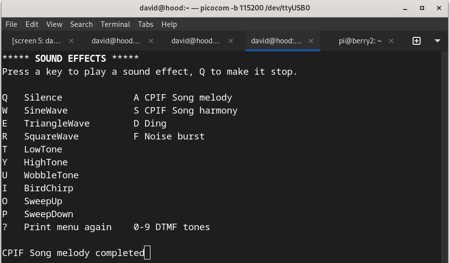
Here is a 25-second recording of my sound effects demo in action: sound effects demo
Credits
Open-source software libraries I used for my MusicBox project:
- rp-hal is an open-source project with APIs for accessing the RP2040 peripherals (UART, I2C, SPI, ADC, etc) from Rust.
- RTIC Real-Time Interrupt-Driven Concurrency - kind of like a real-time OS in Rust for embedded systems.
Design
The goal of my MusicBox project is to have fun creating my own microcontroller-based hardware and software to play sound effects and music on small speakers. I wanted to use the smallest number of parts possible while still getting reasonably good audio quality. Preferably I wanted to use parts I already had on hand in my toolbox.
Turning digital signals into sound
A microcontroller is a digital device. Its output pins only produce binary 1's and 0's, represented as 3.3 volts for a 1 and ground for 0. Sound is analog, continuous in nature, not binary. A speaker is driven by electrical currents that need to vary in proportion to the sounds it is trying to produce. To bridge the divide between digital and analog, we need to do digital-to-analog conversion. The RP2040 microcontroller chip I'm using is really good at PWM (Pulse Width Modulation), so that was what I used for to drive the speaker.
What is PWM?
PWM stands for Pulse Width Modulation. It means rapidly turning a digital output signal on and off for varying amounts of time (pulse widths).
For example, most light dimmers use PWM to control the brightness of a lamp or LED light. The PWM signal turns the light on and off 60 times per second or faster, quicker than the eye can notice. The percent of the time the PWM signal is turned on is called the duty cycle. If the PWM signal is on 10% of the time and off 90% of the time, it has a 10% duty cycle. Applied to the light dimmer, it means the light shines at 10% of its maximum brightness.
See: What is PWM: Pulse Width Modulation
How did I use PWM to drive a speaker?
The Suggested RP2040 PWM Audio Design
I looked at the RP2040 hardware design notes section 3.4.1 PWM Audio. Their suggested design uses a PWM output signal connected to a filter circuit consisting of two capacitors and three resistors:
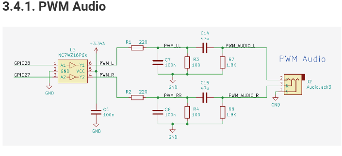
This design does not meet my requirements:
- It produces a signal too weak to drive a speaker
- It therefore needs to be connected to an audio amplifier
- Buying an amplifier doesn't give me as much DIY joy as making my own
- Buying an amplifier doesn't make use of the parts I already have
My PWM Speaker Driver Design
I researched audio amplifiers to find out how to build my own audio amplifier to turn a weak, filtered PWM signal into a strong one that could drive a speaker. I found that modern audio amplifiers use a class D amplifier design. The class D design has benefits over the older class A and AB designs because it doesn't experience crossover distortion.
See: What is a a Class-D Amplifier, and What Are They Useful For?
This example class D amplifier design comes from an Analog Devices technical article Class D Amplifiers: Fundamentals of Operation and Recent Developments:
When I looked at this diagram, that's when I had my "aha!" moment. A class D amplifier turns an analog input signal into a PWM signal, and then uses that PWM signal to rapidly switch a speaker "off" and "on", just like a light switch dimmer or a PWM variable-speed motor controller.
Why use a capacitor filter to turn my PWM output signal into a weak analog signal just so a class D amplifier can turn it back into a PWM signal to drive a speaker? I already have a PWM signal!
My design combines analog to digital conversion and signal amplification in one step, by using the classic H-bridge technique used for controlling motors.
This diagram comes from an article titled "What is an H-Bridge?" and shows the basic layout of an H-bridge motor controller circuit:
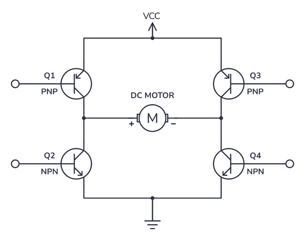
An H-bridge circuit lets you run a motor backward or forward by changing the direction of current through the motor. By using PWM signals as the inputs to the H-bridge you can control not only the direction but the speed of the motor, by varying the PWM duty cycle.
A motor and a speaker have a lot in common: they are inductive in nature because they basically involve putting a electrical current through a coil of wire. In my case instead of making a motor run backwards and forwards I'm sending current in alternating directions through a speaker to make the speaker diaphram move forwards or backwards. I vary the duty cycle to vary the strength of the current and therefore the power of the audio signal.
Here is my speaker driver circuit design:
This design only requires 4 transistors, 4 diodes, 4 resistors, 2 1.5V batteries, and a speaker. I already had these parts on hand.
Why are there diodes in the circuit? As I mentioned above, the speaker has an inductive coil and therefore I need diodes to protect the circuit from inductive kickback.
Avoiding the Hazard of Transistor Burnout
People experienced in electronics might notice that this design requires very careful timing to ensure that for example transistors Q1 and Q2 are never both turned on at the same time. That hazard is called "shoot through" and will cause your transistors to overheat and burn out.
These particular BJT transistors take 225 ns to turn off but only 15 ns to turn on. I programmed the microcontroller to include "dead zone" timing to make sure that for each pair of transistors, one transistor was turned off for 225 ns before the other transistor starts turning on. I carefully checked the timing of the PWM signals with an oscilloscope before connecting the transistor outputs together.
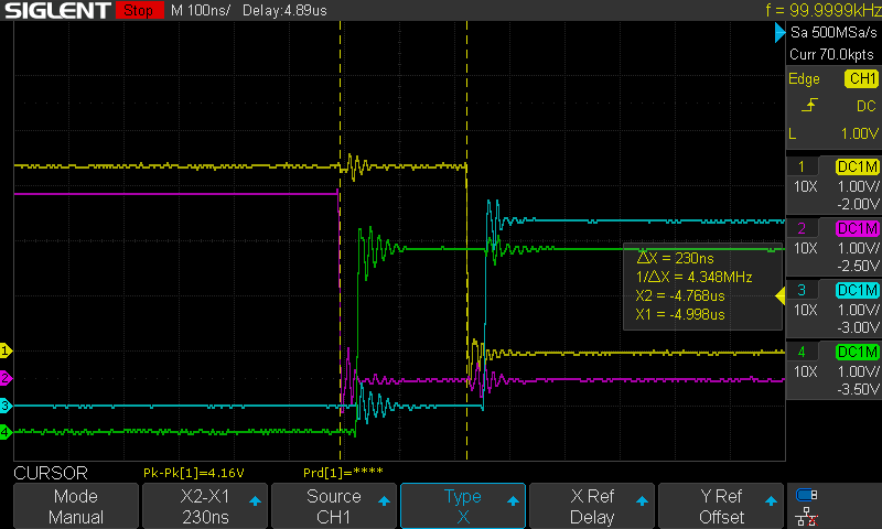
In the oscilloscope screenshot above:
- Yellow (channel 1) is Pico pin 6 controlling transistor Q1
- Red/violet (channel 2) is Pico pin 7 controlling transistor Q2
- Blue (channel 3) is Pico pin 16 controlling transistor Q3
- Green (channel 4) is Pico pin 17 controlling transistor Q4
Q1 and Q3 are PNP transistors, which means that a low signal turns them on.
Q2 and Q4 are NPN transistors, which means that a high signal turns them on.
In this oscilloscope trace you can see that the yellow and red signals start out high, meaning Q1 is off and Q1 is on. (If you are confused please go back and read the previous two paragraphs about PNP vs NPN transistors.) At the left vertical dashed line the red signal goes low, meaning Q2 starts to turn off. At the right vertical dotted line, you see that the yellow signal goes low, meaning Q1 starts to turn on. The time difference between the two vertical dashed lines is the "dead zone" when both are turned off. The oscilloscope shows that the dead zone is 230 ns, which meets the requirement that it be at least 225 ns. (N.B. ns = nanosecond, one billionth of a second. These are precise timing requirements!)