Construction
Parts List
- Raspberry Pi Pico microcontroller board
- A 3.3V-compatible USB-to-serial adapter. I recommend USB to TTL Serial Cable Debug / Console Cable for Raspberry Pi from Adafruit.
- A breadboard for plugging parts into and wiring them up. Something like this breadoard from Micro Center would work just fine.
- Wires for connecting pins on a breadboard. Being frugal, I use random small guage wire that I scavenge from various sources. They need to be the right thickness to plug into the breadboard holes. You can buy breadboard jumper wires made for the purpose. You'll need about 30 wires of various lengths.
- 2 2N4403 transistors
- 2 2N4401 transistors
- 4 general-purpose silicon diodes, like 1N4001
- 4 1K-ohm resistors
- 2 breadboard-friendly bushbutton switches, like these switches from Sparkfun
- 1 breadboard-friendly single-pole double-throw switch able to handle 200mA, like Mini Power Switch from Sparkfun
- 1 small 8-ohm speaker rated between 250mW and 1W, like this speaker from Mouser
- Battery holder for 2 D-sized batteries
- 2 D-sized batteries
- Solder for a couple of small soldering jobs
The amount of soldering I did on this project is extremely minimal. Mainly I just soldered two wires onto the speaker so I had some way to connect it to the breadboard. Your battery holder will need wires soldered to it if it doesn't already have them.
Part substitutions:
Batteries
I don't think I needed D-sized batteries. AA batteries might work. They have to supply about 200mA current at 3V. The batteries just supply the current through the speaker. The microncontroller is powered via a USB connector.
Transistors
The 2N4403 and 2N4401 BJT transistors are listed as "obsolete" on some websites. I'm using some left over from my Electrical Engineering student days from the 1990s. The main thing is to use complementary PNP / NPN BJT transistors that can are rated at 600mA and don't have a turnoff time much higher than 225 ns. I use the BJTs in full-saturation switching mode in an H-bridge configuration. The software I wrote assumes a 225 ns turn-off time to avoid shoot-through on the H-bridge. If you substitute transistors that turn off much more slowly than that, then you will need to tweak my software to have a longer dead time when switching, or your circuit will burn up.
I am using BJTs instead of MOSFETs because I could not find MOSFETs that met my requirements:
- Must be breadboard-friendly with pins at 0.1" / 2.54mm pitch
- Must quickly switch on and off up to 200mA current
- Must turn fully on with only 3.3V Vgs
Everything I found when searching for MOSFETs either needed 5V Vgs or higher to turn fully on, had a large gate capacitance such that the microcontroller couldn't switch them quickly, or were surface-mounted parts unusable on a breadboard. You can buy MOSFET drivers to handle the high gate capacitance and level shift from 3.3v to the required gate voltage. But with that additional cost and space and complexity, I might as well just buy an audio amplifier - defeating the whole purpose of this project, which is to build my own!
So I'm using my old BJTs as switches and they work just fine.
Wire Connections
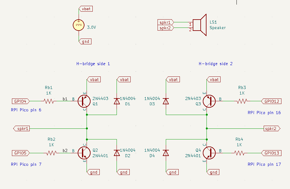
Speaker Driver Schematics
Raspberry Pi Pico pin diagram

Connections to make on Raspberry Pi Pico
Pin 1 (UART0 TX): white wire on USB-to-serial adapter (host RX)
Pin 2 (UART0 RX): green wire on USB-to-serial adapter (host TX)
Pin 3 (GND): black wire on USB-to-serial adapter (host ground)
Pin 6 (GPIO4): to resistor driving Q1 (see schematic)
Pin 7 (GPIO5): to resistor driving Q2 (see schematic)
Pin 8 (GND): battery ground
Pin 16 (GPIO12): to resistor driving Q3 (see schematic)
Pin 17 (GPIO13): to resistor driving Q4 (see schematic)
Pin 18 (GND): battery ground
Pin 28 (GND): battery ground
Pin 29 (GPIO22): app pushbutton. Connect other side of pushbutton to ground.
Pin 30 (RUN): reset pushbutton. Connect other side pushbutton to ground.
If you are going to program the Pico, connect it to a host PC via USB cable.
If the Pico is already programmed, then you can connect it to either a PC or to a power adapter. Either way, the Pico gets its power via its USB connection.
Other connections
The battery holder holds 2 D batteries in series. The black wire is ground, the red wire is +3 volts. (assuming your battery holder uses standard wire colors.)
The single-pole double-throw (SPDT) switch is used as a on-off switch for the battery. It has 3 pins that I'll call top, middle, and bottom. Connect top to battery red, middle to the red power row the breadboard, and bottom to nothing.
Connect the battery black wire to the ground row on both sides of the breadboard.
Connect one of the speaker wires to the H-bridge side 1 spkr1 output (see schematic) and the other speaker wire to the H-bridge side 2 spkr2 output (see schematic).
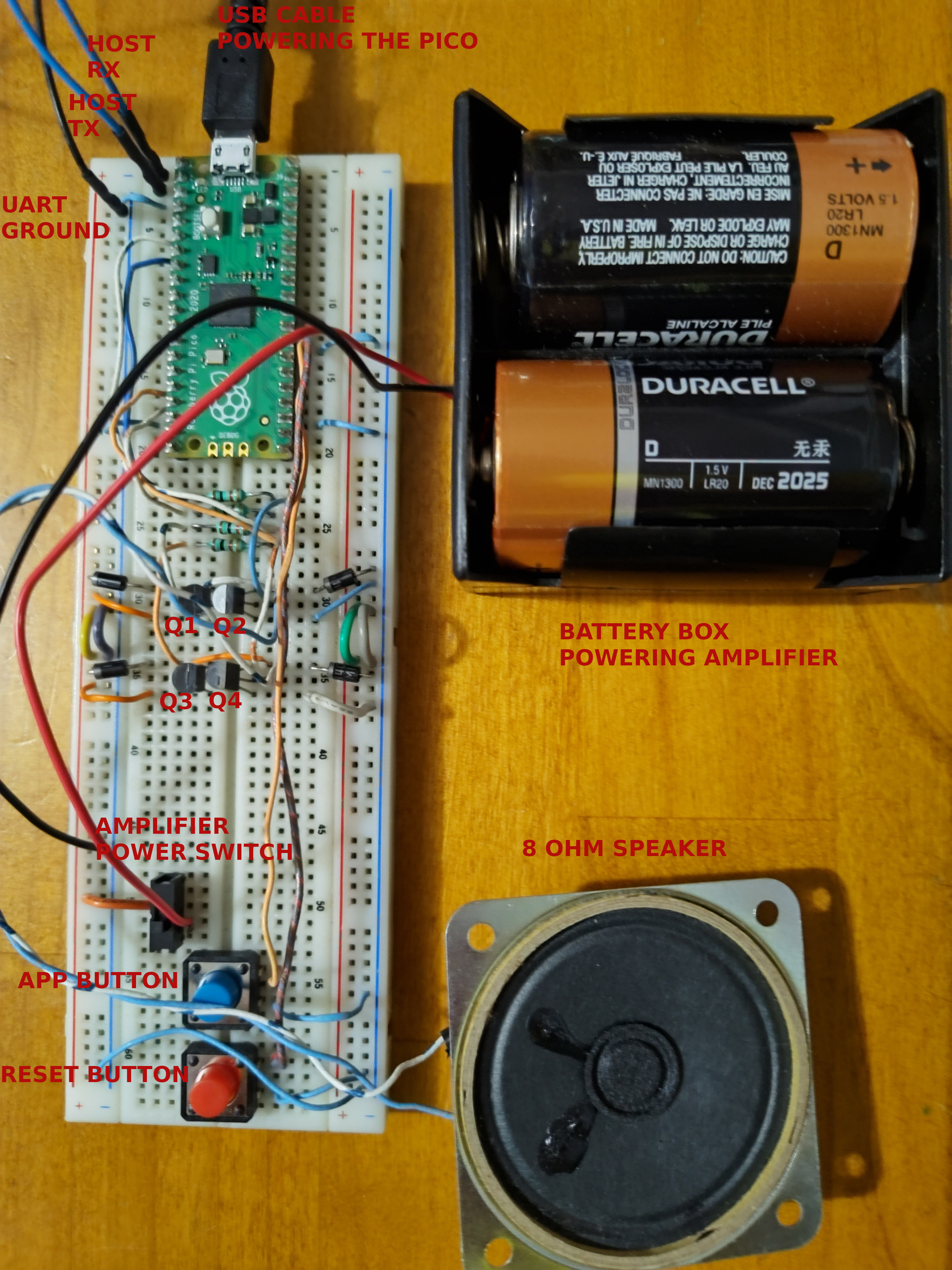
Final Assembly
Don't worry that the "host RX" and "host TX" wires shown in the picture below are both blue instead of white and green, respectively, as described in the connection list above. The picture below was taken of a MusicBox device connected to a Raspberry Pi single-board computer instead of to a PC, so no USB-serial adapter was needed. Instead I just connected directly to the UART RX/TX pins on the Raspberry Pi GPIO header.